
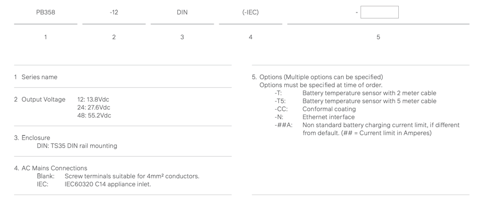
The PB358-DIN(-IEC) series is a family of 13.8Vdc, 27.6Vdc and 55.2Vdc, 138W, TS35 DIN rail mounted, off-line battery chargers / DC uninterruptible power supplies which operate from 220/240Vac mains power. When connected to a lead acid battery, these units provide uninterrupted power to critical DC loads in the event of a mains failure.
Key Features
- Models PB358-DIN-IEC employ an IEC60320 C14 appliance inlet which provides a pluggable AC mains connection
- Features Battery Connection Test (Battery Disconnect Alarm) and Battery Condition Testing (BCT) for preventative maintenance purposes.
- Independent rectifier and battery charging current limit
- Front panel adjustable battery charge current limiting
- Switch-selectable 2-Step or 3-Step Charger
- Automatic and Manual Battery Conditioning Test (BCT)
- Inbuilt Battery Low Voltage Disconnect (LVD)with Front Panel Battery Start Switch
- Four Form-C Alarm Relays and four Alarm/Status LEDs (Mains OK, Rectifier OK, Battery OK and Fault)
- Ethernet Interface Option Available -N
Applications
- Security and Building Automation
- Industrial Automation
PB358-DIN(-IEC) SERIES BATTERY CHARGERS / DC UPS
The PB358-DIN(-IEC) series is a family of 13.8Vdc, 27.6Vdc and 55.2Vdc, 138W, TS35 DIN rail mounted, off-line battery chargers / DC uninterruptible power supplies which operate from 220/240Vac mains power. When connected to a lead acid battery, these units provide uninterrupted power to a DC load in the event of a mains failure.
PB358-DIN(-IEC) contains independent rectifier and battery charging current limiting, front panel adjustable battery charge current limiting, a switch-selectable two or three step float/fast charger, a battery low voltage disconnect switch / electronic circuit breaker in the battery positive, automatic battery disconnections/battery fuse fail testing, optional battery temperature probe for battery float voltage temperature compensation, front panel battery start button, automatic and manual battery condition testing (BCT), four form-C alarm relays and four alarm/status LEDs (Mains OK, Rectifier OK, Battery OK and Fault). It employs very high efficiency switching technology, combined with low output noise.
PB358-DIN(-IEC) is supplied in a 63 x 123 x 133mm (WxHxD) Aluminium enclosure for mounting on a TS35 DIN rail. Models PB358-DIN employ screw terminal blocks for the AC mains input, and DC and battery outputs. Models PB358-DIN-IEC employ an IEC60320 C14 appliance inlet which provides a pluggable AC mains connection. Alarm and control terminations are via pluggable push-in spring-connections terminal blocks.
All models employ natural convection cooling and are rated to 100% rated output (138W) at Ta = 0-50°C, derating linearly to 50% rated output (69W) at Ta = 70:°C.
PB358-DIN(-IEC) is available with a 10BaseT / 100BaseTX Ethernet interface (option –N).
MODEL SUMMARY
|
MODEL |
PB358-12DIN(-IEC) |
PB358-24DIN(-IEC) |
PB358-48DIN(-IEC) |
|
Total Load + Charge Power |
138W |
138W |
138W |
|
DC Output |
13.8V 10.0A |
27.6V 5.0A |
55.2V 2.5A |
|
Battery Charge Current Limit |
0.5 - 10.0A Setpoint: 2.0A |
0.2 - 5.0A Setpoint: 1.0A |
0.1 - 2.5.0A Setpoint:0.5A |
|
Size |
63.0 x 123 x 133mm (W x H x D) |
||
|
Weight |
775g |
||
PB358-DIN(-IEC) Ordering information
FEATURES AND OPERATION
Below is an extensive summary of the features and operation of the PB358-DIN Battery Charger / DC Uninterruptible Power Supply Series.
AC/DC CONVERTER (RECTIFIER):
A high efficiency switching AC/DC converter (rectifier) provides 13.8Vdc / 10A, 27.6Vdc / 5A or 55.2Vdc / 2.5A directly to the load and to charge the battery. This converter provides a constant output voltage and a constant current limit. Latching output overvoltage shutdown and auto-resetting overtemperature protection are also included.
BATTERY PROTECTION:
Low Voltage Disconnect Switch and Electronic Circuit Breaker:
The battery is connected across the output of the AC/DC converter via an electronic low voltage disconnect switch (LVD switch) in the positive lead. As a result, the output and battery voltage are essentially equal and the battery is available to supply the load the instant AC mains power fails. Also, the output voltage follows the battery voltage as the battery charges or discharges.
To protect the battery against overdischarge, the electronic LVD switch disconnects the positive load terminal from the positive battery terminal when the battery voltage drops below 1.75V/cell (10.5V, 21.0V or 42.0V) for at least 10 seconds.
This switch recloses on reapplication of AC mains power. For this switch to operate correctly, the corresponding terminals of the battery and load must not be connected together outside of the PB358-DIN (-IEC).
The LVD switch also operates as a self-resetting electronic circuit breaker. This protects the load wiring against overcurrent conditions or accidental short circuits. This circuit breaker trips in nominally 300mS for load currents greater than 150% of the rectifier output current rating (15A/12V models, 7.5A/24V models and 3.75A/48V models). This threshold does not change if AC mains power is present (the rectifier is operating) or absent (the rectifier is off). For larger overcurrent conditions, the time-current characteristics approximately follow the characteristics of 32V or 58V mini blade fuses (10A / I2t = 93A2s for 12V models, 7.5A / I2t = 68A2s for 24V models and 4A / I2t = 17A2s for 48V models).
To manually reset the LVD switch when AC mains voltage is not available, a battery start push-button is provided on the front panel of the unit. By pushing this button for approximately one second the microcontroller closes the LVD switch providing battery power to the load. The battery start push-button can then be released and the LVD switch will stay closed. The load will then operate from the battery until the battery becomes fully discharged and the LVD switch reopens. All electronic circuit breaker operations are functional during battery start and these protect the LVD switch if it is turned on into an overload or short circuit.
Battery Charge Current Limiter:
Battery charging current is controlled by its own constant current limiter. This controller reduces the AC/DC converter output voltage to limit the maximum charging current into the battery. This current limiter can be set to suit the installed battery capacity (typically 0.1C10). This protects the battery against excessive charging currents. This current limiter can be adjusted from marginally above 0A to the full output rated current of the PB358-DIN (-IEC) by a potentiometer on the front of the unit. It is set at the factory to 2A (12V models), 1A (24V models) and 0.5A (48V models). Alternate settings can be advised at time of order by adding the subscript -##A to the end of the model number, where ##A is the requested battery charging current limit. Alternatively, this control can be adjusted following the procedure in “Adjustment of Battery Charging Current Limiter”. This current limiter has no effect on the output current available to the load from the rectifier.
The load can draw up to the full rated current from the PB358-DIN (-IEC) at all times. If the battery is charging, its charging current will be limited by the rectifier current limit, less the load current or the battery charge current limiter, whichever is lower."
Battery Fuse:
The unit is protected against battery reverse polarity by a front panel battery fuse in series with the battery positive terminal. This is a 15A/32V mini blade fuse on 12 and 24V models and a 15A/58V mini blade fuse on 48V models.
CONTROL & MONITORING:
Advanced monitoring and control functions are provided by an embedded microprocessor;
Battery Charging Operation:
The PB358-DIN(-IEC) can operate as either a 2-Step float charger or a 3-Step fast charger. The charger algorithm is selected by DIP Switch 2 on the front panel of the unit.
2 STEP CHARGER:
A 2 Step charger algorithm is typically chosen when the battery charging current limit is less than or equal to 0.1C10(10% of the system battery’s 10 hour capacity). Operation of this charger is shown in Figure 2.
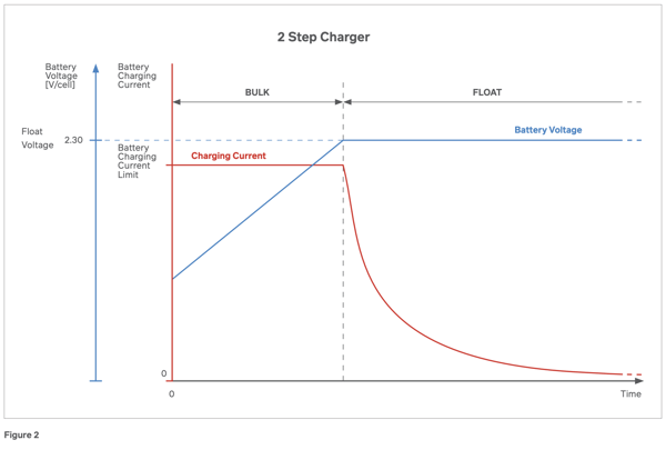
The charger has two modes of operations as follows:
- BULK: If the battery is discharged and mains voltage is applied, the AC/DC converter (rectifier) provides constant current charging into the battery. This current limit is controlled by the battery charge current limiter or the rectifier current less the load current, whichever is lower.
- FLOAT: Once the battery voltage has risen to float voltage, the battery charger operates as a constant voltage charger. The float voltage is set to 2.3V/cell (13.8Vdc/12V models, 27.6Vdc/24V models and 55.2Vdc/48V models). If a battery temperature sensor is connected to the PB358-DIN(-IEC) than this is the float voltage at 25°C. The battery can be charged at this voltage indefinitely and it has been set to maintain the battery at 100% charge without overcharging it. This value has been selected to suit most AGM VRLA batteries.
3 STEP (FAST) CHARGER:
A 3 Step charger algorithm is typically chosen when the battery charging current limit is greater than 0.1C10(10% of the system battery’s 10 hour capacity). This allows the battery to be charged at a faster rate than than a conventional 2 step charger. Operation of this charger is shown in Figure 3.
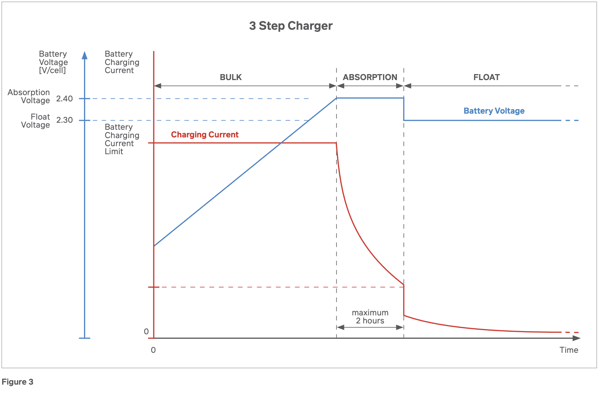
The charger has three modes of operations as follows:
- BULK: If the battery is discharged and mains voltage is applied, the AC/DC converter (rectifier) provides constant current charging into the battery. This current limit is controlled by the battery charge current limiter or the rectifier current less the load current, whichever is lower.
- ABSORPTION: If the battery charger has been in BULK mode,a s the battery charges its voltage is allowed to rise to the absorption voltage. The battery charger then operates as a constant voltage charger at this setpoint. This allows the charging current into the battery to remain high for longer and to charge the battery faster. This absorption voltage is set to 2.40V/cell (14.4Vdc/12V models, 28.8Vdc/24V models and 57.6Vdc/48V mode. If a battery temperature sensor is connected to the PB358-DIN(-IEC) then this absorption voltage is at 25°C.
Long term charging of the battery at the absorption voltage would cause overcharging and damage to the battery. Therefore, the battery charger terminates the absorption mode and changes to FLOAT mode under either of the following conditions:
-
- The battery charging current has dropped to less than 4% if the PB358-DIN(IEC)’s rating (400mA/12V model, 200mA/24V models and 100mA/48V models). This is referred to as the “absorption taper current”.
- The battery charger has been in absorption mode for longer than 2 hours and the battery charging current has not dropped below the absorption taper current.
- FLOAT: In ‘Float Mode’ the battery charger operates as a constant voltage charger at the float voltage setpoint. The float voltage is set to 2.3V/cell (13.8Vdc/12V models, 27.6Vdc/24V models and 55.2Vdc/48V models). If a battery temperature sensor is connected to the PB358-DIN(-IEC) then this is the float voltage at 25°C. The battery can be charged at this voltage indefinitely and it has been set to maintain the battery at 100% charge without overcharging it. This value has been selected to suit most AGM VRLA batteries.
Technical Note
Once the battery charger is in FLOAT mode, its mode can only change to BULK. This mode change occurs when the battery starts to discharge during an AC mains failure or if an overload current greater than the rectifier current limit is drawn by the load. To prevent overcharging the battery with repeated short duration AC mains failures or overloads, the charger mode cannot re-enter ABSORPTION mode until the battery voltage has dropped below 2.00V/cell (12Vdc/12V models, 24Vdc/24V models and 48Vdc/48V models). If the AC mains power returns or the overload is removed before the battery drops below 2.0V/Cell, the battery charger mode will change from BULK back to FLOAT once the battery voltage has risen to the float voltage.
LEDs and Relays:
The PB358-DIN(-IEC) Series provides the following LEDs and Relays for system monitoring and/or control purposes. Comprehensive information on LED flash codes and Relay operations can be found in the Operation and Installation Manual (available on request). A summary of the LEDs and Relays available is as follows:
LEDs:
Four multi-functional LEDs are provided to display operation/alarm status and diagnostic codes.
- MAINS OK LED
- RECTIFIER OK LED
- BATTERY OK LED
- FAULT LED
All LEDs employ different rates of continuous flashing and counted flash codes.
Relays:
Four voltage-free changeover relay contacts (32Vdc, 1A) are provided to indicate alarms and status. Relay connections are via the 16 way alarm terminal block located on the front panel of the unit. Available RELAYs include:
- MAINS STATUS RELAY
- RECTIFIER STATUS RELAY
- BATTERY OK RELAY - 2 modes of operation available
- FAULT RELAY
When the PB358-DIN(IEC) is off, all relays go to the FAULT/OFF state.
Battery Condition Test (BCT):
To identify if the battery is ageing and needs to be replaced, the PB358-DIN (-IEC) can be configured to perform a Battery Condition Test (BCT) on a scheduled basis. This function is enabled using DIP switch 1 on the front panel.
During a BCT, the battery float voltage setpoint is reduced for an extended period of time (1 hour) so that the battery supplies all of the load power for this duration. The embedded microcontroller monitors the battery voltage and raises a BCT FAIL alarm if the battery voltage drops below the programmed threshold (2.04V/cell, 12.24V/12V models, 24.48V/24V models, 48.96V/48V models) before the end of the test duration. The FAULT LED flashes four times every five seconds and the FAULT relay (default) or BATT OK relay (if DIP switch 3 is ON) goes to fault state (NO/COM = closed, NC/COM = open).
This alarm remains latched until it is reset manually by pressing the CONTROL button for one second. If the battery voltage is greater than this threshold at the end of the test duration, the test is passed and no alarm is raised.
During a BCT, the BATT OK LED flashes continuously at 10 flashes per second. If DIP switch 3 is in the ON position, the FAULT relay is configured to show the state of the BCT. In this case, during a BCT the FAULT relay (BCT STATE) is ON/BCT ACTIVE (NO/COM = open, NC/COM = closed). If the load is too small for the BCT to be meaningful, the FAULT relay (BCT STATE) can be used to switch in additional loads during the BCT.
If BCT is enabled, it will occur automatically once per week.
An automatic BCT can only be performed on a fully charged battery. To ensure this, an automatic BCT will only start once the battery charger has been in float mode for at least 24 hours.
A BCT can be started manually at any time and with the battery in any state of charge. This is done by pressing and holding the CONTROL button for five seconds, until the BATT OK LED flashes at 5 times per second.
Any BCT, automatic or manual, can be aborted manually by pressing and holding the CONTROL button for five seconds.
The BCT parameters (Duration = 1 hour, Fail threshold voltage = 2.04V/cell, and Interval = 1 week) are not field-adjustable. Alternate parameters can be requested at time of order. Contact Powerbox.
The default BCT parameters have been set for installations which have large batteries where these batteries are sized to provide typically 20 - 24 hours of backup on failure of AC mains power. It is advised that BCT be disabled for installations with small batteries and short backup times to prevent false BCT FAIL alarms.
Battery Connections Test (Battery Disconnected Alarm):
On power up or on microcontroller reset, after the battery charger enters float mode and then every five minutes while in float mode, the embedded microcontroller tests the battery connections and battery fuse. It momentarily reduces the battery charger’s float voltage setpoint causing the load to be supplied by the battery. If no battery is connected, if the battery wiring is faulty or if the battery fuse has been blown, the microcontroller asserts a BATTERY DISCONNECTED alarm. The FAULT LED flashes once every five seconds and either the FAULT relay (default) or BATT OK relay (if DIP switch 3 is ON) goes to fault mode (NO/COM = closed, NC/COM = open). This alarm remains latched until it is reset. It will reset
automatically when the cause of the fault is remedied (battery is replaced, wiring fault is repaired or blown battery fuse is replaced). This fault can also be reset by depressing the CONTROL button for one second.
Battery connections tests are only performed when the battery charger is in float mode.
Battery Low Voltage Alarm:
The PB358-DIN will display a Battery Low Voltage alarm when the battery voltage drops below 1.80V/cell (10.8V/12V models, 21.6V/24V models and 43.2V/48V models). The BATT OK LED will be OFF and the BATT OK relay goes to fault mode (NO/COM = closed, NC/COM = open). This alarm resets when the battery voltage rises to 0.17V/cell above this threshold (11.8V/12V models, 23.6V/24V models and 47.2V/48V models).
The battery low voltage alarm threshold voltage is fixed.
External Shutdown Input:
The rectifier can be shut down remotely by connecting a voltage-free contact to the external shutdown input on the 16 way alarm/control terminal block on the front panel.
When this contact is closed, the rectifier shuts off and the load is powered by the battery. This function allows external circuitry to test the performance of the battery. If no battery is connected to the unit, the output and battery voltage drops to approximately 9.6V (12V models), 19.4V (24V models) or 39.1V (48V models) when this contact is closed.
During external shutdown, the RECT OK LED and the RECT OK relay indicate a rectifier fault. Mains status, rectifier overtemperature, battery low voltage, battery overvoltage and battery over temperature functions remain operational, BCT is inhibited or aborted and battery connections tests are inhibited once the battery voltage drops and the charger state changes to BULK. External shutdown does not clear latched battery fault indications.
Rectifier Over temperature Power Limit:
If the ambient temperature is too high for the output power being drawn from the rectifier or if there is insufficient space around the PB358-DIN (-IEC) for proper natural convection cooling, the embedded microcontroller will reduce the output power from the rectifier to limit its internal temperature to prevent it from being damaged. The RECT OK LED flashes
continuously at 10 flashes per second to indicate this fault and the RECT OK relay goes to fault state (NO/COM = closed, NC/COM = open).
This alarm resets automatically when sufficient cooling air is available to lower the rectifier temperature below its temperature limit setpoint.
D-Rating Curve:
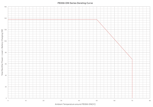
How do I correctly size a power supply?
The sum of the battery charging current and the continuous load current must be kept less than or equal to the rated output current of the rectifier at the required maximum ambient temperature.
Example:
An installation must supply a 13.8V continuous load of 6A and charge a 20Ah backup battery in a maximum ambient temperature of 55°C. The battery requires a maximum charging current of 2A (0.1C). The sum of the load current and maximum battery charging current is 6A + 2A = 8A. Multiplying by the float voltage gives a maximum output power of 13.8V x 8A = 110.4W.
Referring to the derating curve, model PB358-12DIN has a maximum rated output power of 120.75W at 55°C so it is suitable for this application.
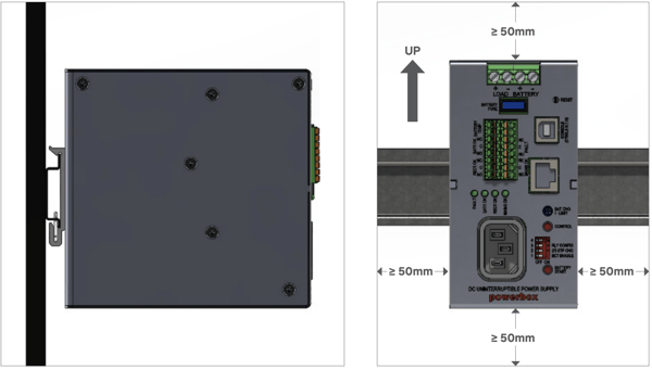
Mounting:
The PB358-DIN (-IEC) series is designed to be mounted on a TS35 DIN rail in the vertical plane as shown below.
To provide fire protection, a non-combustible plate must be mounted below the unit or the unit must be installed inside an enclosure complying with AS/NZS60950.1, Cl. 4.6.2 or AS/NZS62368.1, Cl. 6.4.8
Contact us for more information